How to Generate Alerts Based on SNMP Traps

,

Generating Alerts Based on SNMP Traps

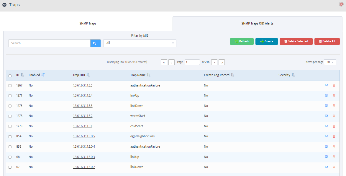
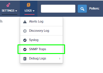
Step 1: Login to the Nectus portal, go to the Logs -> SNMP Traps.


Graphical user interface, application Description automatically generated


Step 2: You will see two Tabs “SNMP Traps” and “SNMP Trap OID Alerts”.

“SNMP Traps” Tab contain list of all the SNMP Traps received by Nectus server from all the network devices.

“SNMP Trap OID Alerts” Tab contains list of pre-configured (default) alert rules for different SNMP traps.


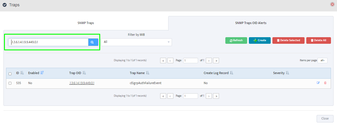
You can search if specific SNMP Trap OID already have an alert rule defined and enable it.


Graphical user interface, text, application Description automatically generated


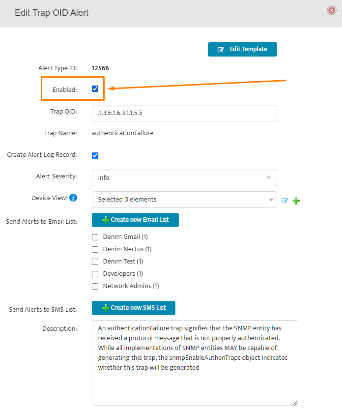
If alert rule already exists, you just need to activate it  by clicking on “Enable” button inside the rule.


Graphical user interface, text, application Description automatically generated


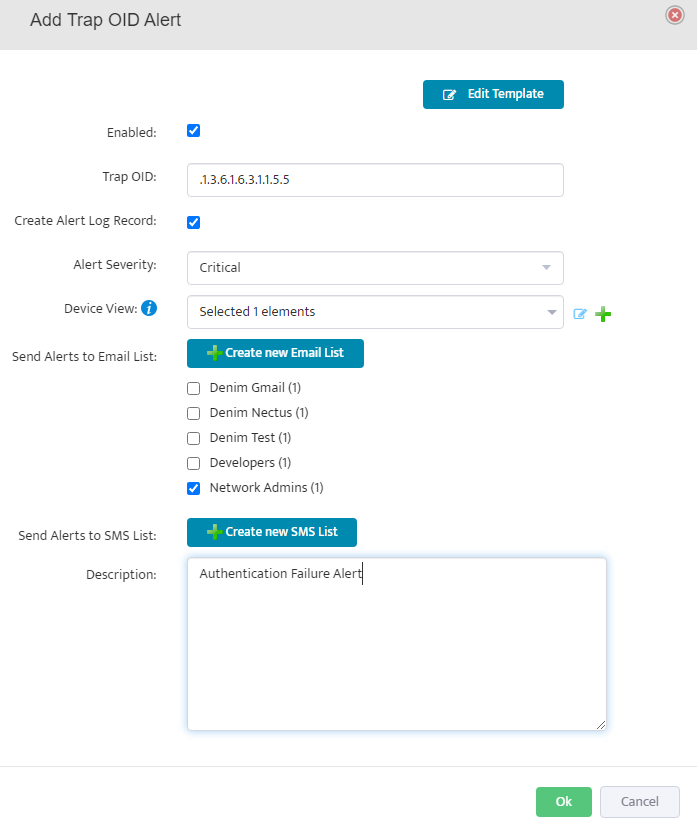
Step 3: If there is no rule exists, click on “Create” button to create a new alert rule.


Graphical user interface, text, application Description automatically generated


Complete all the required alert rule parameters.


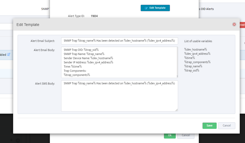
Step 4: Click on “Edit Template” to review and adjust the Alert template format

Graphical user interface, text, application Description automatically generated


Done.

How to collect Interface-VLAN membership info from Cisco Switch via SNMP (CISCO-VLAN-MEMBERSHIP-MIB)

,

How to collect Interface-VLAN membership info from Cisco Switch via SNMP (CISCO-VLAN-MEMBERSHIP-MIB)


CISCO-VLAN-MEMBERSHIP-MIB contain several usefull OIDs for collecting Interface VLAN membership information from Cisco Swithes

1.3.6.1.4.1.9.9.68.1.2.2.1.1 (vmVlanType)

1.3.6.1.4.1.9.9.68.1.2.2.1.2 (vmVlan)

1.3.6.1.4.1.9.9.68.1.2.2.1.3 (vmPortStatus)

1.3.6.1.4.1.9.9.68.1.2.2.1.4 (vmVlans)

1.3.6.1.4.1.9.9.68.1.2.2.1.5 (vmVlans2k)

1.3.6.1.4.1.9.9.68.1.2.2.1.6 (vmVlans3k)

1.3.6.1.4.1.9.9.68.1.2.2.1.7 (vmVlans4k)


Lets see what our LAB switch reports on these for Interface with ifIndex = [4]


OID VLAN Memership Type: 1.3.6.1.4.1.9.9.68.1.2.2.1.1

1 = static, 2 = dynamic, 3 = multiVlan

Output Example: ‘1.3.6.1.4.1.9.9.68.1.2.2.1.1.4’ => “1” (VLAN statically assigned to this port)


OID VLAN ID of the Port: 1.3.6.1.4.1.9.9.68.1.2.2.1.1

Output Example: ‘1.3.6.1.4.1.9.9.68.1.2.2.1.2.4′ => “104” (Port is assigned to VLAN 104)


OID Port Status: 1.3.6.1.4.1.9.9.68.1.2.2.1.3

1 = Inactive, 2 = Active, 3 = Shutdown

Output Example: ‘1.3.6.1.4.1.9.9.68.1.2.2.1.3.4’ => “2” (Port is Active)


How to collect list of VLANs from Cisco Switch via SNMP (CISCO-VTP-MIB)

,

How to collect list of VLANs from Cisco Switch via SNMP (CISCO-VTP-MIB)

CISCO-VTP-MIB contain several useful OID for collecting VLAN information from Cisco Switches


1.    1.3.6.1.4.1.9.9.46.1.3.1.1.1 (vtpVlanIndex)

2.    1.3.6.1.4.1.9.9.46.1.3.1.1.2 (vtpVlanState)

3.    1.3.6.1.4.1.9.9.46.1.3.1.1.3 (vtpVlanType)

4.    1.3.6.1.4.1.9.9.46.1.3.1.1.4 (vtpVlanName)

5.    1.3.6.1.4.1.9.9.46.1.3.1.1.5 (vtpVlanMtu)

6.    1.3.6.1.4.1.9.9.46.1.3.1.1.6 (vtpVlanDot10Said)

7.    1.3.6.1.4.1.9.9.46.1.3.1.1.7 (vtpVlanRingNumber)

8.    1.3.6.1.4.1.9.9.46.1.3.1.1.8 (vtpVlanBridgeNumber)

9.    1.3.6.1.4.1.9.9.46.1.3.1.1.9 (vtpVlanStpType)

10.    1.3.6.1.4.1.9.9.46.1.3.1.1.10 (vtpVlanParentVlan)

11.    1.3.6.1.4.1.9.9.46.1.3.1.1.11 (vtpVlanTranslationalVlan1)

12.    1.3.6.1.4.1.9.9.46.1.3.1.1.12 (vtpVlanTranslationalVlan2)

13.    1.3.6.1.4.1.9.9.46.1.3.1.1.13 (vtpVlanBridgeType)

14.    1.3.6.1.4.1.9.9.46.1.3.1.1.14 (vtpVlanAreHopCount)

15.    1.3.6.1.4.1.9.9.46.1.3.1.1.15 (vtpVlanSteHopCount)

16.    1.3.6.1.4.1.9.9.46.1.3.1.1.16 (vtpVlanIsCRFBackup)

17.    1.3.6.1.4.1.9.9.46.1.3.1.1.17 (vtpVlanTypeExt)

18.    1.3.6.1.4.1.9.9.46.1.3.1.1.18 (vtpVlanIfIndex)


Note that output from out Lab Switch did not return any values for first OID: 1.3.6.1.4.1.9.9.46.1.3.1.1.1


VLAN State: 1.3.6.1.4.1.9.9.46.1.3.1.1.2

1 = Operational, 2 = Suspended, 3 = mtuTooBigForDevice, 4 = mtuTooBigForTrunk

‘1.3.6.1.4.1.9.9.46.1.3.1.1.2.1.1’ => “1”

‘1.3.6.1.4.1.9.9.46.1.3.1.1.2.1.10’ => “1”

‘1.3.6.1.4.1.9.9.46.1.3.1.1.2.1.100’ => “1”

‘1.3.6.1.4.1.9.9.46.1.3.1.1.2.1.101’ => “1”

‘1.3.6.1.4.1.9.9.46.1.3.1.1.2.1.102’ => “1”

‘1.3.6.1.4.1.9.9.46.1.3.1.1.2.1.109’ => “1”

‘1.3.6.1.4.1.9.9.46.1.3.1.1.2.1.1000’ => “1”

‘1.3.6.1.4.1.9.9.46.1.3.1.1.2.1.1001’ => “1”

‘1.3.6.1.4.1.9.9.46.1.3.1.1.2.1.1002’ => “1”

‘1.3.6.1.4.1.9.9.46.1.3.1.1.2.1.1003’ => “1”

‘1.3.6.1.4.1.9.9.46.1.3.1.1.2.1.1004’ => “1”

‘1.3.6.1.4.1.9.9.46.1.3.1.1.2.1.1005’ => “1”


VLAN Type: 1.3.6.1.4.1.9.9.46.1.3.1.1.3

1 = Ethernet, 2 = FDDI, 3= TokenRing, 4 = FDDI, 5 = rtNet, 6 = Depreciated

‘1.3.6.1.4.1.9.9.46.1.3.1.1.3.1.1’ => “1”

‘1.3.6.1.4.1.9.9.46.1.3.1.1.3.1.10’ => “1”

‘1.3.6.1.4.1.9.9.46.1.3.1.1.3.1.100’ => “1”

‘1.3.6.1.4.1.9.9.46.1.3.1.1.3.1.101’ => “1”

‘1.3.6.1.4.1.9.9.46.1.3.1.1.3.1.102’ => “1”

‘1.3.6.1.4.1.9.9.46.1.3.1.1.3.1.109’ => “1”

‘1.3.6.1.4.1.9.9.46.1.3.1.1.3.1.1000’ => “1”

‘1.3.6.1.4.1.9.9.46.1.3.1.1.3.1.1001’ => “1”

‘1.3.6.1.4.1.9.9.46.1.3.1.1.3.1.1002’ => “2”

‘1.3.6.1.4.1.9.9.46.1.3.1.1.3.1.1003’ => “3”

‘1.3.6.1.4.1.9.9.46.1.3.1.1.3.1.1004’ => “4”

‘1.3.6.1.4.1.9.9.46.1.3.1.1.3.1.1005’ => “5”


VLAN Name: 1.3.6.1.4.1.9.9.46.1.3.1.1.4

‘1.3.6.1.4.1.9.9.46.1.3.1.1.4.1.1’ => “default”

‘1.3.6.1.4.1.9.9.46.1.3.1.1.4.1.10’ => “VLAN0010”

‘1.3.6.1.4.1.9.9.46.1.3.1.1.4.1.100’ => “VLAN0100”

‘1.3.6.1.4.1.9.9.46.1.3.1.1.4.1.101’ => “VLAN0101”

‘1.3.6.1.4.1.9.9.46.1.3.1.1.4.1.102’ => “vlan102”

‘1.3.6.1.4.1.9.9.46.1.3.1.1.4.1.109’ => “VLAN0109”

‘1.3.6.1.4.1.9.9.46.1.3.1.1.4.1.1000’ => “VLAN1000”

‘1.3.6.1.4.1.9.9.46.1.3.1.1.4.1.1001’ => “VLAN1001”

‘1.3.6.1.4.1.9.9.46.1.3.1.1.4.1.1002’ => “fddi-default”

‘1.3.6.1.4.1.9.9.46.1.3.1.1.4.1.1003’ => “token-ring-default”

‘1.3.6.1.4.1.9.9.46.1.3.1.1.4.1.1004’ => “fddinet-default”

‘1.3.6.1.4.1.9.9.46.1.3.1.1.4.1.1005’ => “trnet-default”
 

How to collect list of MAC addresses from Cisco Switch via SNMP (dot1dTpFdbEntry)

,

How to collect list of MAC addresses from Cisco Switch via SNMP (dot1dTpFdbEntry)

One of the ways to get list of MAC addresses from the forwarding table of Cisco switch is via SNMP MIB: dot1dTpFdbEntry

This MIB branch contain three OIDs:

1.3.6.1.2.1.17.4.3.1.1 (dot1dTpFdbAddress)

1.3.6.1.2.1.17.4.3.1.2 (dot1dTpFdbPort)

1.3.6.1.2.1.17.4.3.1.3 (dot1dTpFdbStatus)

1.3.6.1.2.1.17.4.3.1.1 (dot1dTpFdbAddress) contain list of MAC addresses in Binary format

1.3.6.1.2.1.17.4.3.1.2 (dot1dTpFdbPort) contain IfIndex value of the interface associated with each MAC Address

1.3.6.1.2.1.17.4.3.1.3 (dot1dTpFdbStatus) contain Status code which gives information how each MAC was learned by the switch.


To get list of MAC address perform SNMP Get-Bulk request for “.1.3.6.1.2.1.17.4.3.1.1”

Here is the Example of output from our LAB Switch:

‘1.3.6.1.2.1.17.4.3.1.1.0.21.198.146.146.151’ => “ƒ’—”

‘1.3.6.1.2.1.17.4.3.1.1.0.25.185.178.231.213’ => “¹²çÕ”

‘1.3.6.1.2.1.17.4.3.1.1.0.33.216.202.216.128’ => “!ØÊ؀”

‘1.3.6.1.2.1.17.4.3.1.1.0.34.144.251.146.97’ => “”û’a”

‘1.3.6.1.2.1.17.4.3.1.1.0.80.86.156.43.191’ => “PVœ+¿”

‘1.3.6.1.2.1.17.4.3.1.1.0.80.86.156.49.102’ => “PVœ1f”

‘1.3.6.1.2.1.17.4.3.1.1.0.80.86.156.69.113’ => “PVœEq”


Notice that actual MAC Addresses returned look like some garbage characters but those are actually MAC address in ASCII format that needs to be converted to HEX to get a conventional xx:xx:xx:xx:xx:xx style.

Lets take last line: ‘1.3.6.1.2.1.17.4.3.1.1.[0.80.86.156.69.113]’ => “PVœEq”

If we take ASCII text (PVœEq) and convert to HEX,  we will get  50:56:9C:45:71

If we take Decimal [0.80.86.156.69.113] and convert to HEX, we will get 0:50:56:9C:45:71

So we have a MAC address on both sides.


To get list of associated Ports for each MAC address perform SNMP Get-Bulk request for “.1.3.6.1.2.1.17.4.3.1.2”

Here is the Example of output from our LAB Switch:

‘1.3.6.1.2.1.17.4.3.1.2.0.21.198.146.146.151’ => “2”

‘1.3.6.1.2.1.17.4.3.1.2.0.25.185.178.231.213’ => “2”

‘1.3.6.1.2.1.17.4.3.1.2.0.33.216.202.216.128’ => “1”

‘1.3.6.1.2.1.17.4.3.1.2.0.34.144.251.146.97’ => “1”

‘1.3.6.1.2.1.17.4.3.1.2.0.80.86.156.43.191’ => “2”

‘1.3.6.1.2.1.17.4.3.1.2.0.80.86.156.49.102’ => “2”

‘1.3.6.1.2.1.17.4.3.1.2.0.80.86.156.69.113’ => “2”

Values returned represent IfIndex values for corresponding Interfaces associated with each MAC Address. You need to use [ID substring] to match ifIndex value to MAC Address.

And finally, to get a Status code to each MAC address perform SNMP Get-Bulk Request for 1.3.6.1.2.1.17.4.3.1.3


Example of output from our LAB Switch:

‘1.3.6.1.2.1.17.4.3.1.3.0.21.198.146.146.151’ => “3”

‘1.3.6.1.2.1.17.4.3.1.3.0.25.185.178.231.213’ => “3”

‘1.3.6.1.2.1.17.4.3.1.3.0.33.216.202.216.128’ => “3”

‘1.3.6.1.2.1.17.4.3.1.3.0.34.144.251.146.97’ => “3”

‘1.3.6.1.2.1.17.4.3.1.3.0.80.86.156.43.191’ => “3”

‘1.3.6.1.2.1.17.4.3.1.3.0.80.86.156.49.102’ => “3”

‘1.3.6.1.2.1.17.4.3.1.3.0.80.86.156.69.113’ => “3”

Possible Values codes are

1 = Other

None of the following. This would include the case where some other MIB object (not the corresponding instance of dot1dTpFdbPort, nor an entry in the dot1dStaticTable)

is being used to determine if and how frames addressed to the value of the corresponding instance of dot1dTpFdbAddress are being forwarded.

2 = Invalid

This entry is no longer valid (e.g., it was learned but has since aged out), but has not yet been flushed from the table.

3 = Learned

The value of the corresponding instance of dot1dTpFdbPort was learned and is being used.

4 = Self

The value of the corresponding instance of dot1dTpFdbAddress represents one of the bridge’s addresses.

The corresponding instance of dot1dTpFdbPort indicates which of the bridge’s ports have this address.

5 = Mgmt

The value of the corresponding instance of dot1dTpFdbAddress is also the value of an existing instance of dot1dStaticAddress.


Important Note: This process may need to be adjusted if  “per-VLAN” SNMP Contexts being used. In that case you must repeat this process separately for each VLAN by adding “@n” to SNMP community string where “n” is the VLAN ID.

Ruckus Wireless Antenna info SNMP OID

, ,

Ruckus “Antenna Info” SNMP OIDs
===========================

Antenna Type (0 = 802.11bg, 1 = 802.11a, 2 = 802.11ng, 3 = 802.11na, 4 = 802.11ac)

‘1.3.6.1.4.1.25053.1.2.2.1.1.2.2.1.3.[6.108.170.179.26.66.144].[0]’ => “2”
‘1.3.6.1.4.1.25053.1.2.2.1.1.2.2.1.3.[6.108.170.179.26.66.144].[1]’ => “3”

Antenna Gain (dB)
‘1.3.6.1.4.1.25053.1.2.2.1.1.2.2.1.44.[6.108.170.179.26.66.144].[0]’ => “7”
‘1.3.6.1.4.1.25053.1.2.2.1.1.2.2.1.44.[6.108.170.179.26.66.144].[1]’ => “7”

Tx Power Level (0 = Full, 1 = Half, 2 = Quarter, 3 = Eighth)
‘1.3.6.1.4.1.25053.1.2.2.1.1.2.2.1.5.[6.108.170.179.26.66.144].[0]’ => “0”
‘1.3.6.1.4.1.25053.1.2.2.1.1.2.2.1.5.[6.108.170.179.26.66.144].[1]’ => “0”

Channel Number
‘1.3.6.1.4.1.25053.1.2.2.1.1.2.2.1.4.[6.108.170.179.26.66.144].[0]’ => “1”
‘1.3.6.1.4.1.25053.1.2.2.1.1.2.2.1.4.[6.108.170.179.26.66.144].[1]’ => “36”

Number Of Current Users
‘1.3.6.1.4.1.25053.1.2.2.1.1.2.2.1.8.[6.108.170.179.26.66.144].[0]’ => “0”
‘1.3.6.1.4.1.25053.1.2.2.1.1.2.2.1.8.[6.108.170.179.26.66.144].[1]’ => “0”

Utilization (%)
‘1.3.6.1.4.1.25053.1.2.2.1.1.2.2.1.40.[6.108.170.179.26.66.144].[0]’ => “0”
‘1.3.6.1.4.1.25053.1.2.2.1.1.2.2.1.40.[6.108.170.179.26.66.144].[1]’ => “0”

Average Client RSSI (dBm)
‘1.3.6.1.4.1.25053.1.2.2.1.1.2.2.1.9.[6.108.170.179.26.66.144].[0]’ => “0”
‘1.3.6.1.4.1.25053.1.2.2.1.1.2.2.1.9.[6.108.170.179.26.66.144].[1]’ => “0”

Antenna MAC Address
‘1.3.6.1.4.1.25053.1.2.2.1.1.2.2.1.1.[6.108.170.179.26.66.144].[0]’ => “lª³B”
‘1.3.6.1.4.1.25053.1.2.2.1.1.2.2.1.1.[6.108.170.179.26.66.144].[1]’ => “lª³B”

Antenna Mesh Enabled (1 – Yes, 2 = No)
‘1.3.6.1.4.1.25053.1.2.2.1.1.2.2.1.6.[6.108.170.179.26.66.144].[0]’ => “2”
‘1.3.6.1.4.1.25053.1.2.2.1.1.2.2.1.6.[6.108.170.179.26.66.144].[1]’ => “2”

Power Management Enabled (1 = Yes, 0 = No)
‘1.3.6.1.4.1.25053.1.2.2.1.1.2.2.1.18.[6.108.170.179.26.66.144].[0]’ => “1”
‘1.3.6.1.4.1.25053.1.2.2.1.1.2.2.1.18.[6.108.170.179.26.66.144].[1]’ => “1”

Max. Number of Clients Allowed
‘1.3.6.1.4.1.25053.1.2.2.1.1.2.2.1.19.[6.108.170.179.26.66.144].[0]’ => “256”
‘1.3.6.1.4.1.25053.1.2.2.1.1.2.2.1.19.[6.108.170.179.26.66.144].[1]’ => “256”

Antenna Rx Packets
‘1.3.6.1.4.1.25053.1.2.2.1.1.2.2.1.10.[6.108.170.179.26.66.144].[0]’ => “1047794”
‘1.3.6.1.4.1.25053.1.2.2.1.1.2.2.1.10.[6.108.170.179.26.66.144].[1]’ => “5447”

Antenna Rx Bytes
‘1.3.6.1.4.1.25053.1.2.2.1.1.2.2.1.11.[6.108.170.179.26.66.144].[0]’ => “223745214”
‘1.3.6.1.4.1.25053.1.2.2.1.1.2.2.1.11.[6.108.170.179.26.66.144].[1]’ => “1050697”

Antenna Tx Packets
‘1.3.6.1.4.1.25053.1.2.2.1.1.2.2.1.13.[6.108.170.179.26.66.144].[0]’ => “42252”
‘1.3.6.1.4.1.25053.1.2.2.1.1.2.2.1.13.[6.108.170.179.26.66.144].[1]’ => “6080”

Antenna Tx Bytes
‘1.3.6.1.4.1.25053.1.2.2.1.1.2.2.1.14.[6.108.170.179.26.66.144].[0]’ => “8941040”
‘1.3.6.1.4.1.25053.1.2.2.1.1.2.2.1.14.[6.108.170.179.26.66.144].[1]’ => “921628”

Number of Tx Fails
‘1.3.6.1.4.1.25053.1.2.2.1.1.2.2.1.16.[6.108.170.179.26.66.144].[0]’ => “0”
‘1.3.6.1.4.1.25053.1.2.2.1.1.2.2.1.16.[6.108.170.179.26.66.144].[1]’ => “0”

Number of Tx Retries
‘1.3.6.1.4.1.25053.1.2.2.1.1.2.2.1.17.[6.108.170.179.26.66.144].[0]’ => “2875”
‘1.3.6.1.4.1.25053.1.2.2.1.1.2.2.1.17.[6.108.170.179.26.66.144].[1]’ => “8”

Authentication Requests
‘1.3.6.1.4.1.25053.1.2.2.1.1.2.2.1.25.[6.108.170.179.26.66.144].[0]’ => “1”
‘1.3.6.1.4.1.25053.1.2.2.1.1.2.2.1.25.[6.108.170.179.26.66.144].[1]’ => “0”

Authentication Responses
‘1.3.6.1.4.1.25053.1.2.2.1.1.2.2.1.26.[6.108.170.179.26.66.144].[0]’ => “1”
‘1.3.6.1.4.1.25053.1.2.2.1.1.2.2.1.26.[6.108.170.179.26.66.144].[1]’ => “0”

Authentication Success
‘1.3.6.1.4.1.25053.1.2.2.1.1.2.2.1.27.[6.108.170.179.26.66.144].[0]’ => “1”
‘1.3.6.1.4.1.25053.1.2.2.1.1.2.2.1.27.[6.108.170.179.26.66.144].[1]’ => “0”

Authentication Failed
‘1.3.6.1.4.1.25053.1.2.2.1.1.2.2.1.28.[6.108.170.179.26.66.144].[0]’ => “0”
‘1.3.6.1.4.1.25053.1.2.2.1.1.2.2.1.28.[6.108.170.179.26.66.144].[1]’ => “0”

How to work with SNMP v2 Contexts in Nexus 7000

,

This is an example on how to obtain list of IP addresses assigned to Interfaces inside specific SNMP Context on Nexus 7000

Step 1.

Obtain list of all SNMP Contexts by sending SNMP GET Bulk for cContextMappingVrfName (.1.3.6.1.4.1.9.9.468.1.1.1.2)

Response:

‘1.3.6.1.4.1.9.9.468.1.1.1.2.10.109.97.110.97.103.101.109.101.110.116’=>”management”

In this response Nexus 7018 Switch has only one SNMP context with a name “management”


Step 2.

Obtain list of all IP addressses that exist in context “management” by sending SNMP GET Bulk for ipAdEntIfIndex (.1.3.6.1.2.1.4.20.1.2)

Note that for this step step we have append context name to V2 community string

(e.g public@management) to specify that this request is specific for context “management”.

Response:

‘1.3.6.1.2.1.4.20.1.2.10.255.27.34’=>”83886080″

In this response we have IP address [10.255.27.34] and associated interface ifIndex “83886080”


Step 3.

Find interface name with ifIndex 83886080 by sending SNMP GET Bulk for (.1.3.6.1.2.1.2.2.1.2)

Response:

‘1.3.6.1.2.1.2.2.1.2.83886080’ => “mgmt0”


So in these 3 steps we have found that  Interface Mgmt0 has assigned an ip address 10.255.27.34


How to read Cisco device S/N via SNMP?

, ,

During network discovery phase Nectus collects S/N for each device that responds to basic SNMP queries.

One of the problem with Cisco  Devices is that different platforms uses different OID to store S/N.

Following OIDs are being used for Cisco:

.1.3.6.1.2.1.47.1.1.1.1.11.1

.1.3.6.1.2.1.47.1.1.1.1.11.2

.1.3.6.1.2.1.47.1.1.1.1.11.10

.1.3.6.1.2.1.47.1.1.1.1.11.22

.1.3.6.1.2.1.47.1.1.1.1.11.1001

.1.3.6.1.2.1.47.1.1.1.1.11.24555730

.1.3.6.1.4.1.14179.1.1.1.4.0

.1.3.6.1.4.1.2467.1.34.4.0

.1.3.6.1.4.1.437.1.1.3.1.22.0

.1.3.6.1.4.1.9.20.1.1.1.1.3.0.1.3.6.1.4.1.7505.1.1.1.0

.1.3.6.1.4.1.9.6.1.101.53.14.1.5.1

.1.3.6.1.4.1.9.9.92.1.1.1.2.1

.1.3.6.1.4.1.9.3.6.3.0

.1.3.6.1.4.1.3076.2.1.2.22.1.63.0

.1.3.6.1.4.1.9.5.1.2.19.0

.1.3.6.1.4.1.9.9.719.1.9.35.1.47.1

How to get Interfaces’ ifIndex values via SNMP

,

To obtain list of ifIndex values for all interfaces for given device SNMP polling agent has to send

SNMP GET BULK request for the following OID:  .1.3.6.1.2.1.2.2.1.1

Response Example:

‘.1.3.6.1.2.1.2.2.1.1.1’ => “1”
‘.1.3.6.1.2.1.2.2.1.1.2’ => “2”
‘.1.3.6.1.2.1.2.2.1.1.3’ => “3”
‘.1.3.6.1.2.1.2.2.1.1.4’ => “4”
‘.1.3.6.1.2.1.2.2.1.1.5’ => “5”
‘.1.3.6.1.2.1.2.2.1.1.6’ => “6”
‘.1.3.6.1.2.1.2.2.1.1.7’ => “7”
‘.1.3.6.1.2.1.2.2.1.1.8’ => “8”
‘.1.3.6.1.2.1.2.2.1.1.9’ => “9”
‘.1.3.6.1.2.1.2.2.1.1.10’ => “10”
‘.1.3.6.1.2.1.2.2.1.1.11’ => “11”
‘.1.3.6.1.2.1.2.2.1.1.12’ => “12”
‘.1.3.6.1.2.1.2.2.1.1.13’ => “13”
‘.1.3.6.1.2.1.2.2.1.1.14’ => “14”
‘.1.3.6.1.2.1.2.2.1.1.15’ => “15”
‘.1.3.6.1.2.1.2.2.1.1.17’ => “17”

Next Step is to get Interface names by sending SNMP GET BULK request for the following OID:  .1.3.6.1.2.1.2.2.1.2

Response Example:

‘.1.3.6.1.2.1.2.2.1.2.1’ => “TenGigabitEthernet0/0/0”
‘.1.3.6.1.2.1.2.2.1.2.2’ => “TenGigabitEthernet0/0/1”
‘.1.3.6.1.2.1.2.2.1.2.3’ => “GigabitEthernet0/0/0”
‘.1.3.6.1.2.1.2.2.1.2.4’ => “GigabitEthernet0/0/1”
‘.1.3.6.1.2.1.2.2.1.2.5’ => “GigabitEthernet0/0/2”
‘.1.3.6.1.2.1.2.2.1.2.6’ => “GigabitEthernet0/0/3”
‘.1.3.6.1.2.1.2.2.1.2.7’ => “GigabitEthernet0/0/4”
‘.1.3.6.1.2.1.2.2.1.2.8’ => “GigabitEthernet0/0/5”
‘.1.3.6.1.2.1.2.2.1.2.9’ => “Crypto-Engine0/0/8”
‘.1.3.6.1.2.1.2.2.1.2.10’ => “GigabitEthernet0”
‘.1.3.6.1.2.1.2.2.1.2.11’ => “Null0”
‘.1.3.6.1.2.1.2.2.1.2.12’ => “Port-channel1”
‘.1.3.6.1.2.1.2.2.1.2.13’ => “Port-channel2”
‘.1.3.6.1.2.1.2.2.1.2.14’ => “Port-channel2.599”
‘.1.3.6.1.2.1.2.2.1.2.15’ => “Port-channel2.11”
‘.1.3.6.1.2.1.2.2.1.2.17’ => “Port-channel2.3213”

Now we are able to match Interface name to an ifIndex value.

Please note unless ifIndex persistence is enabled router (or switch) may assign different ifIndex value to the same interface after reboot.

To enable consistent ifIndex-to-Interface mapping ifIndex persistence must be enabled.

Configuration example for Catalyst 6500

Router(config)# snmp-server ifindex persist

Globally enables SNMP ifIndex persistence.


SNMPv3 Configuration example for IOS-XR (ASR9k)

,

IOS-XR SNMP v3 configuration example for username “user_des”


  1. snmp-server group admins v3 priv
  2. snmp-server user user-des admins v3 auth md5 “authpass” priv des56 “privpass” SystemOwner


this configuration will use MD5 hash for authentication and DES cipher (DES56) for encryption.

IOS-XR (as of 5.3.4 code) also supports

3DES  – 168 bit 3DES algorithm for encryption
AES – 128 bit AES algorithm for encryption