Using Graphs in Custom Dashboards

,

Using Graphs in Custom Dashboards

Nectus offers extensive capabilities of visualizing different aspects of network performance and presenting it in custom dashboards.

This article guides you through the basic step of process of adding graphs to custom dashboards.

Step 1. Prepare Graphs for the Dashboard.

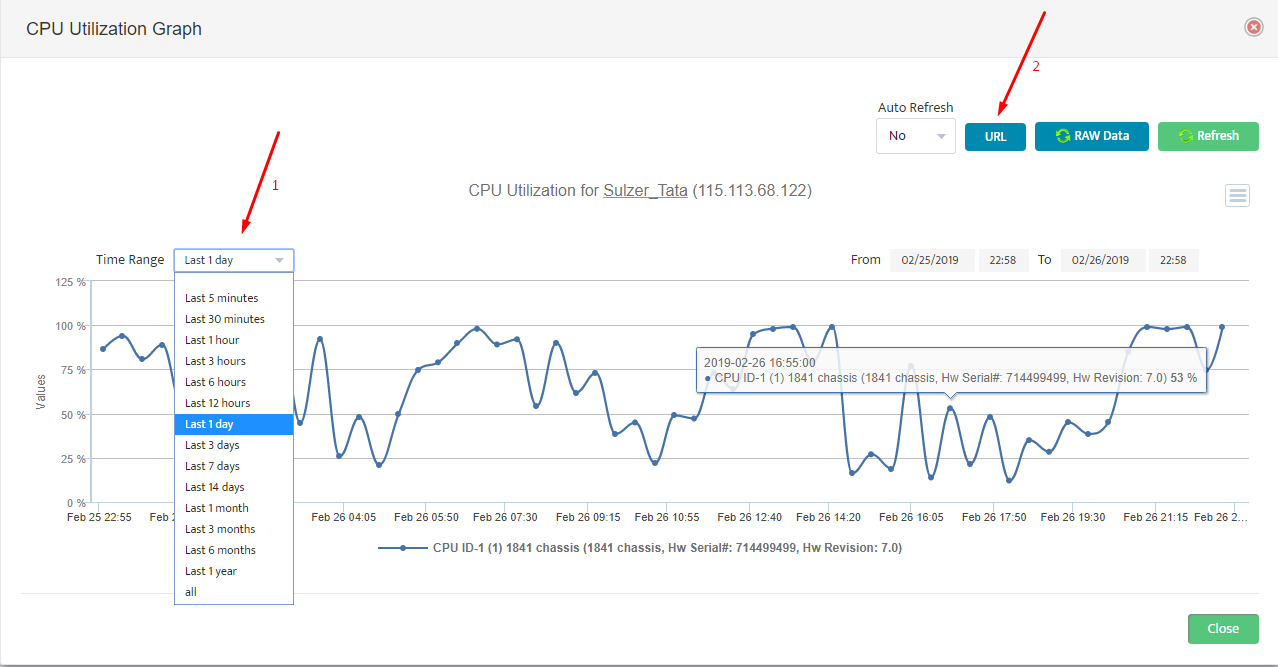
Generate the graph you’d like to include in a dashboard. Make sure to adjust the required time range using the drop-down menu in the left upper corner.

Click URL button to obtain the URL address for the graph.

In the URL window, click Copy and save the URL address into Notepad.

If creating a dashboard with multiple different graphs, repeat building graphs and save URLs for every graph that will be included in dashboard.

Step 2. Create Custom Dashboard.

Once you have built the graphs and saved all the URLs, you are now ready to create a custom dashboard.

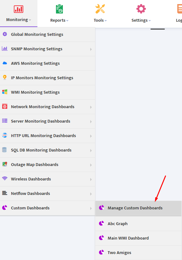
Go to Monitor → Custom Dashboards → Manage Custom Dashboards.

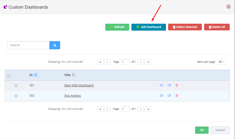
Click Add Dashboard button.

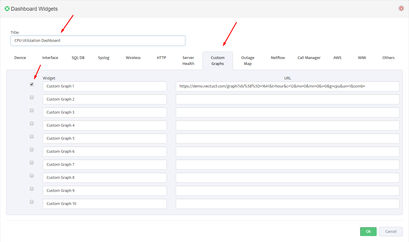
In the “Dashboard Widgets” menu select “Custom Graphs” Tab, select the number of graphs you’d like to display in Dashboard by checking the boxes on the left, and paste the URL addresses that you previously saved.

Give Dashboard a Name and press “Ok”

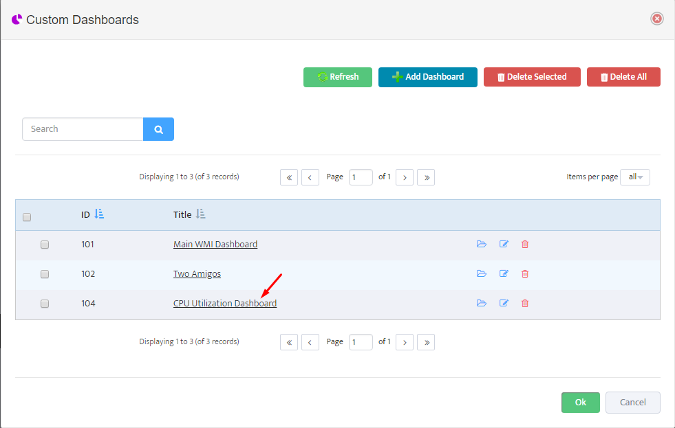
Your new dashboard is now listed in the Custom Dashboards list. Click on the name to open it.

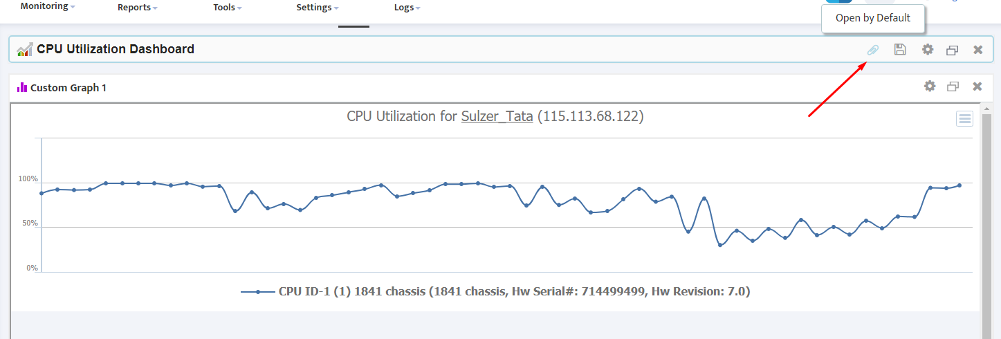
If desired, use paper clip icon in the right upper corner to make this dashboard appear every time you login.


Using Custom SNMP Trackers in Nectus

,

Using Custom SNMP Trackers in Nectus

Nectus offers extensive SNMP based network monitoring capabilities that allow users to track any metrics accessible via SNMP.

In addition to standard metrics, such as CPU, RAM or TCAM utilization, Nectus offers a new feature called “Custom SNMP Tracker” that allows you to monitor virtually any metrics accessible via SNMP.

This article will guide you through the basic steps required for setting up custom SNMP trackers in Nectus.

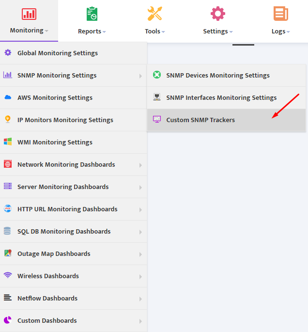
In the Main Menu, go to Monitoring → SNMP Monitoring Settings → Custom SNMP Trackers.

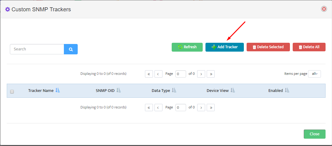
This opens a “Custom SNMP Trackers” window. To create a new custom SNMP Tracker, click the Add Tracker button.

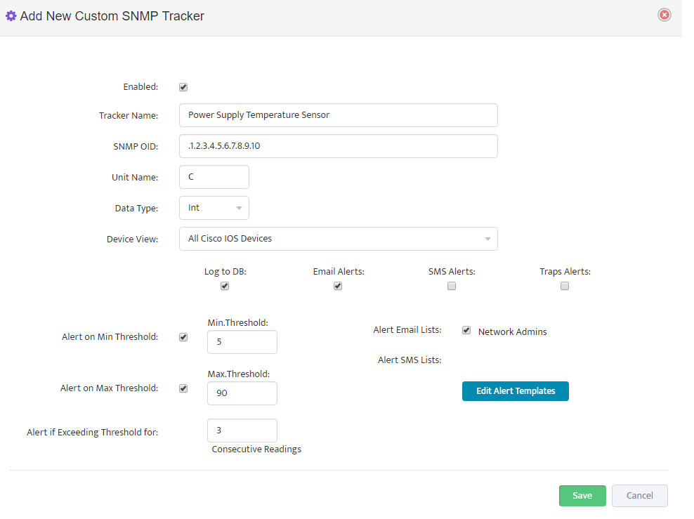
In the “Add New Custom SNMP Tracker” interface box that appears, specify the following parameters:

  1. Tracker name (Example: “Power Supply Temperature Sensor”)
  2. SNMP OID to be used with “SNMP GET” request for Data
  3. Unit Name (Example: C for Temperature)
  4. Data Type (Integer or Floating)
  5. The Device View that contains list of devices to be used for collecting data from
  6. Select “Log to DB” if you would like to save metrics values to a database every 5 minutes
  7. Select “Email Alerts” if you would like to be alerted when metrics exceeds pre-defined thresholds
  8. Min and Max Threshold Values
  9. Select the number of “Consecutive Readings” exceeding threshold that would trigger an alert
  10. Select one of the existing email lists/groups to receive the alerts (Example: “Network Admins”).
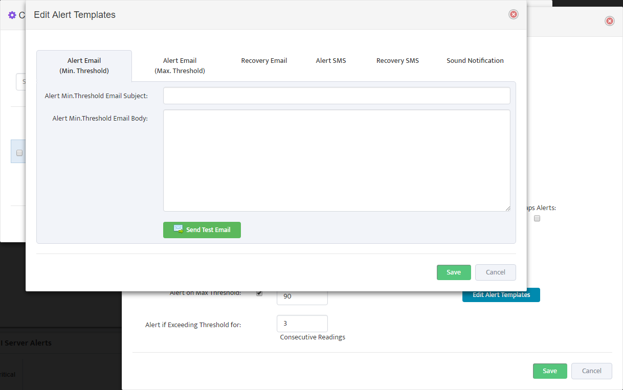
  11. Click Edit Alert Templates to fully customize the alert email for the metric

Customize the E-mail template for Alert and for Recovery event when Metric value returns to normal range.

You have now created your first custom SNMP tracker. To create additional trackers, use “Clone” feature to create and edit a copy of an existing tracker available from the “Custom SNMP Trackers” page.


Monitoring Cisco IPSec VPN Tunnels with Nectus

,

Monitoring Cisco IPSec VPN Tunnels with Nectus

One of the key features introduced in Nectus 1.2.51 is ability to automatically discover and monitor Cisco IPSec VPN Tunnels terminated on ASA Firewalls and regular IOS routers.

  1. Tunnel Discovery

As part of regular scheduled network discovery Nectus attempts to detect existing VPN tunnels on all routers and firewalls by polling standard SNMP MIB: CISCO-IPSEC-FLOW-MONITOR-MIB

reserved for VPN Tunnels.

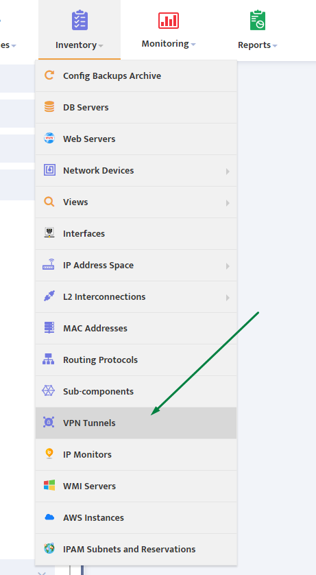
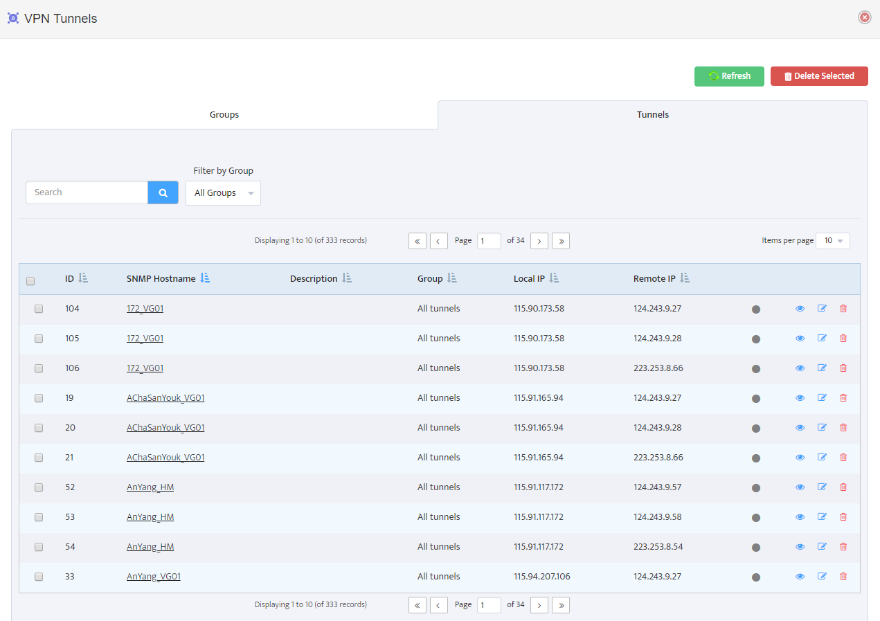
All discovered VPN tunnels can be seen in Main menu: Inventory → VPN Tunnels


All discovered tunnels displayed as a table with Terminating Device, Group, Local and Remote IP Address visible in individual columns.

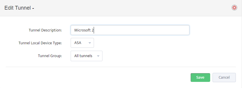
You can assign a human friendly name to each tunnel by pressing Tunnel Edit button on the right.


  1. Creating Groups and Assigning Tunnels to Groups

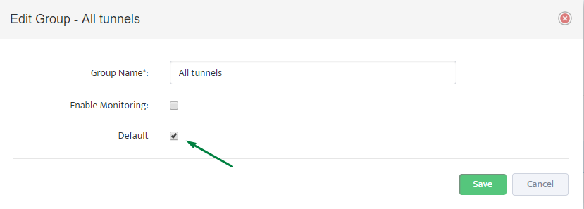
Each Tunnel must be assigned to an individual group with newly discovered Tunnels being automatically assigned to a group with “Default” parameter set to On.

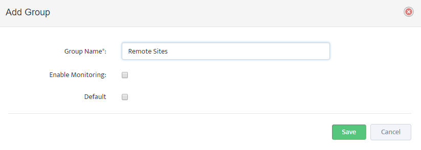
User can create multiple different groups and group tunnels in any way that is appropriate.

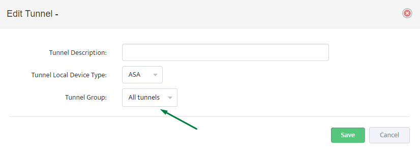
User can change Tunnel-to-Group assignment by using context menu or by using “Edit VPN Tunnel” button.


  1. Enabling Tunnel Monitoring

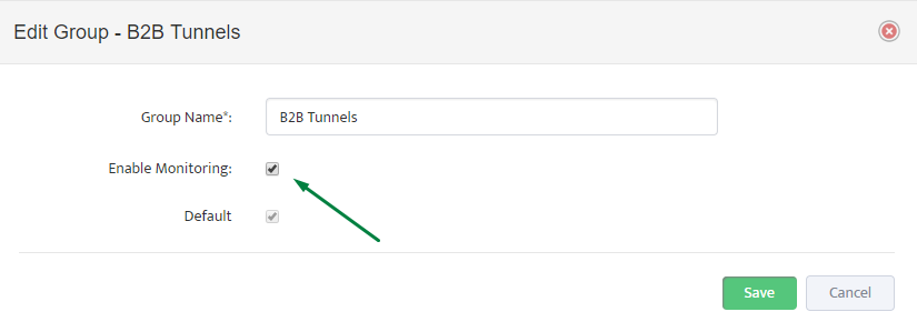
Once all Tunnels are discovered and added to a correct group you can enable monitoring on group level by setting “Enable Monitoring” check-button to “ON”


After “Enable Monitoring” flag is set to ON, Nectus starts checking Tunnel’s status every 5 min and creating records in Alert log along with sending Alert emails in case if Tunnel is down.


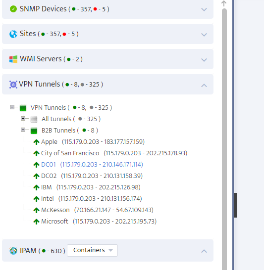
Real Time status for all tunnels can be seen in left side panel “VPN Tunnel”

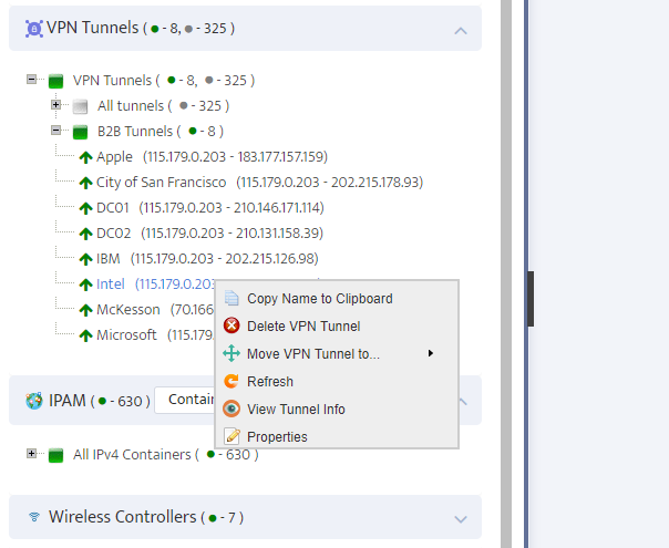
By using right-click on Tunnel’s name you can access rich context menu where you can move tunnels to a different group, delete Tunnel, change Tunnel’s name or

View Tunnel’s Phase 1 and Phase 2 Information.


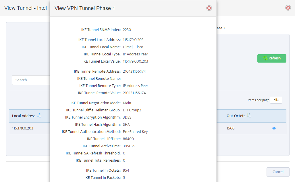
“View Tunnel Info” provides low level Phase 1


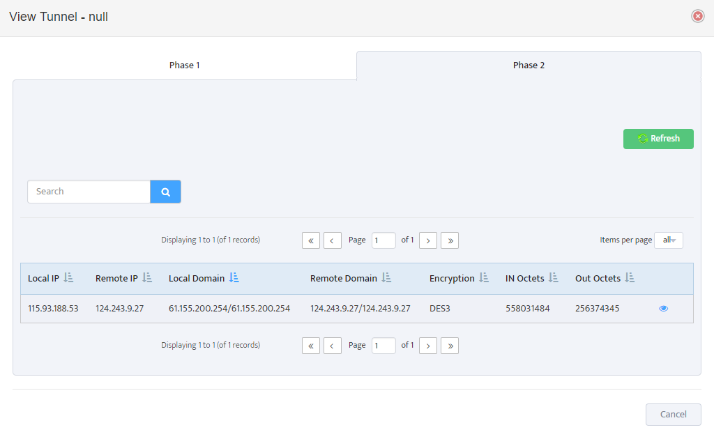
And Phase 2 Information along with encryption domain parameters and traffic counters


Nectus Installation Procedure

,

Nectus Installation Procedure

Server Requirements:   Windows Server 2012 or newer.  8GB of RAM.

1. File Preparation

You start with downloading Nectus Distribution File from www.nectus5.com

Download the ZIP file called Nectus 1.2.51.zip and extract it to a temporary folder.

In the folder you will find two files:


Keep the htdocs.zip file compressed. Start installation by launching file Nectus Setup 1.2.51.exe

2. Nectus Installation

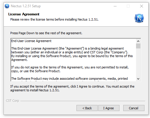
Accept the license agreement on the first page.


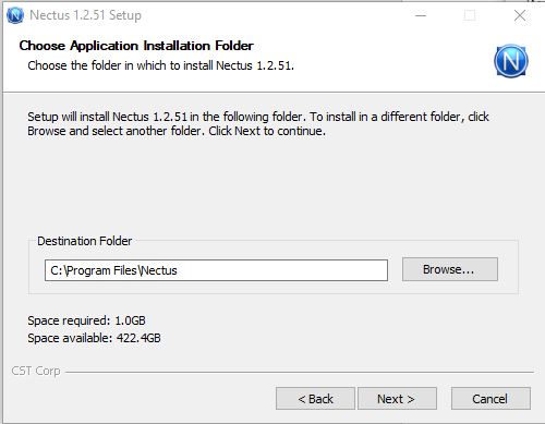
Choose an application installation folder.


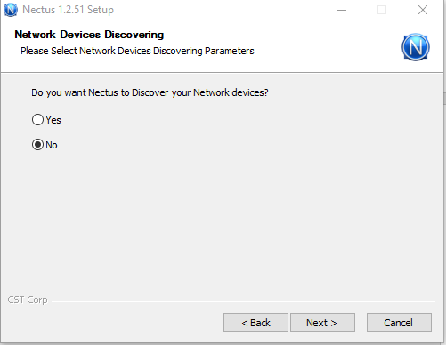
Choose whether you want Nectus to discover Network devices or not.


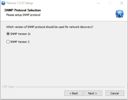
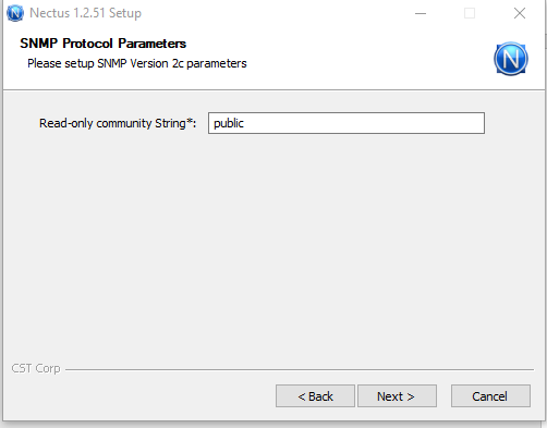
If you selected “Yes” for the Network Device Discovery, Specify the version of the SNMP Protocol.


Then specify SNMP credentials.


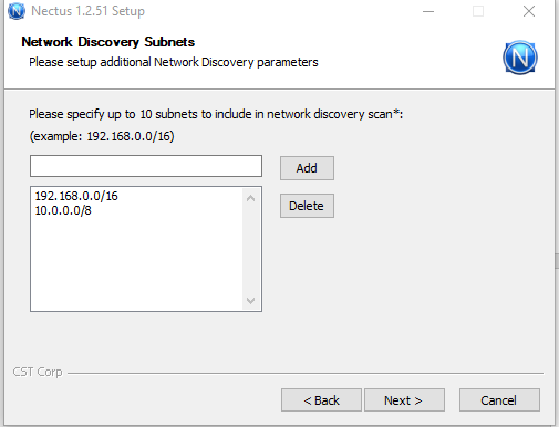
Specify up to 10 IP Subnets where Nectus will be performing Network Discovery.


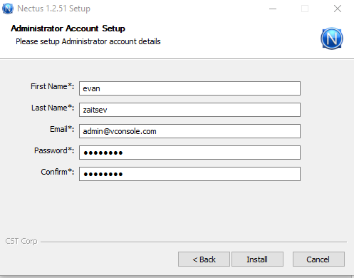
Setup an Administrator account.


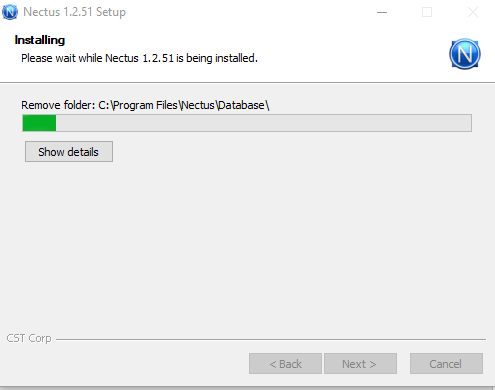
Then click install, which will automatically complete installation.


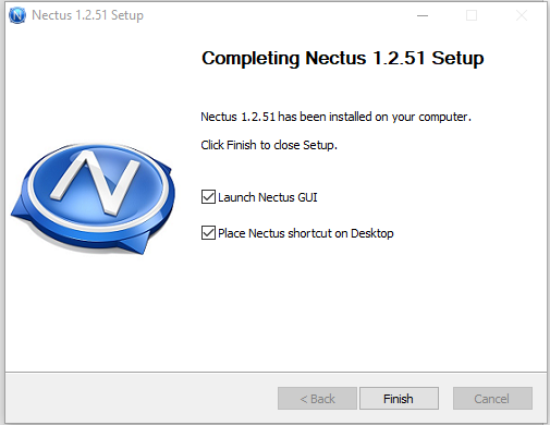
When the installation Is complete, you will see the following page.


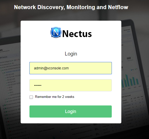
After you click Finish, the Nectus login page will come up, where you need to provide the credentials of the admin account you created during Installation.


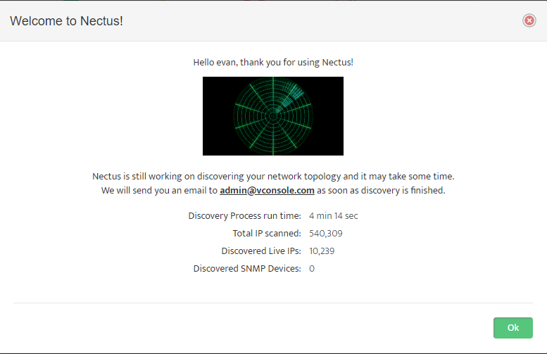
when you log into Nectus you will see a Network Discovery Progress page.


Click “OK” to close it.

3. License Generation

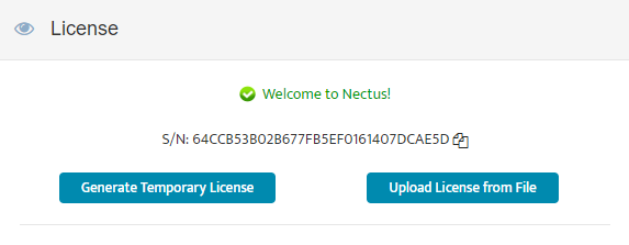
Next, the license page will come up.

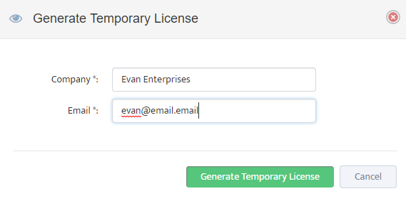
If you do not have a permanent license ready, Click “Generate Temporary License” button.


Complete the “Temporary License” Form and press the “Generate Temporary License” button.

Nectus server must have an Internet access to successfully generate the temporary license.

After temporary license is generated, Nectus is fully operational and ready to be used.


Configuring Network Device Configuration Backup in Nectus 1.2.51

,

Network Device Configuration Backup

Nectus version 1.2.51 introduced several enhancements for Network Device Configuration backup procedure.

User can now use different backup credentials and fully customizable backup scripts for different Device Views. This allows user to create different backup scripts for different vendors or different product lines with different CLI.

User can control what configuration information is included in configuration backup and include supplementary information such as hardware inventory info, current ports status and list of connected devices to a scheduled configuration backup process.

Creating Device View for Configuration Backups

Very first step in setting up your configuration backup is to create Device Views that will contain devices that require common Credentials and Configuration Scripts.

For example, you can create Device View that will contain all Cisco ASA Firewalls and Separate Device View that will contain all Cisco IOS Devices.

The reason those devices require separate Device Views is that Configuration Backup script differ for ASA and IOS devices.

Also use different Device View if devices require different login credentials.

To Create a Device Views, go to Inventory → Views → SNMP Device Views


Creating Login Credential Sets

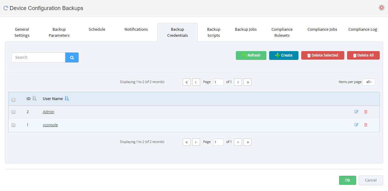
Next step is to define your login credentials that will be used by Configuration backup engine to login to devices and executing Backup Scripts.

To Create a Backup login Credentials, go to:

Settings → Device Configuration Backups → Backup Credentials

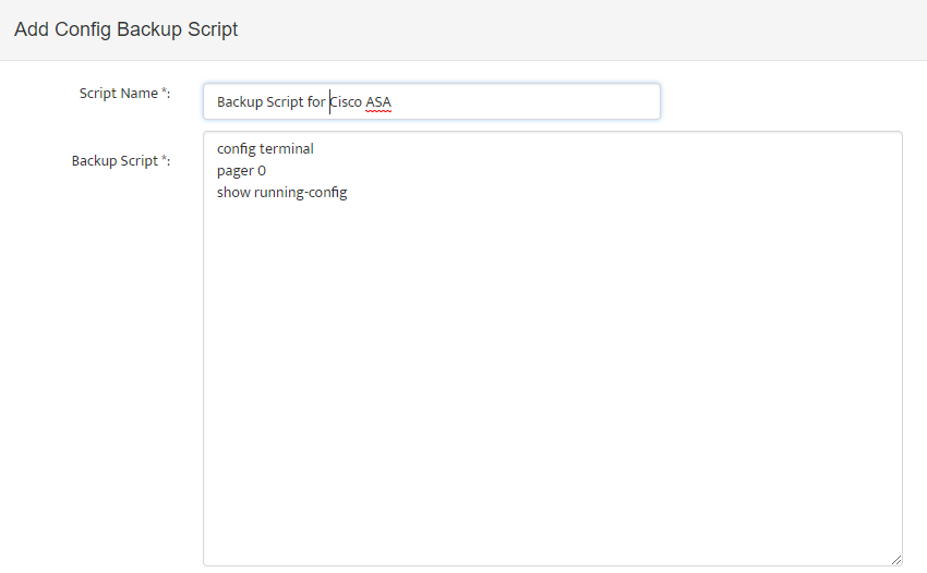
Creating Backup Scripts

Next step is to create Backup Scripts that will be executed by backup engine once it is logged in to device.

Here is the example of sample Backup Script for Cisco ASA Devices:

config terminal

pager 0

show running-config

You can further enhance backup script by including for example hardware inventory information command: “show inventory” etc.

It is important to create a script that will generate all the information required for backup without pagination.

To Create Backup Scripts, go to:

Settings → Device Configuration Backups → Backup Scripts

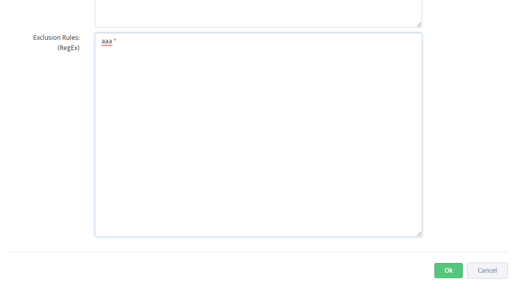
In some cases, output generated by backup script may contain highly sensitive information that may not be desired to be stored anywhere.

For cases like this Nectus offers “exclusion rules” option in Configuration Script definition where you can define which config lines must be excluded from the text before it is stored in database.

You can use RegEx syntax to define those exclusion rules.

Creating Backup Jobs

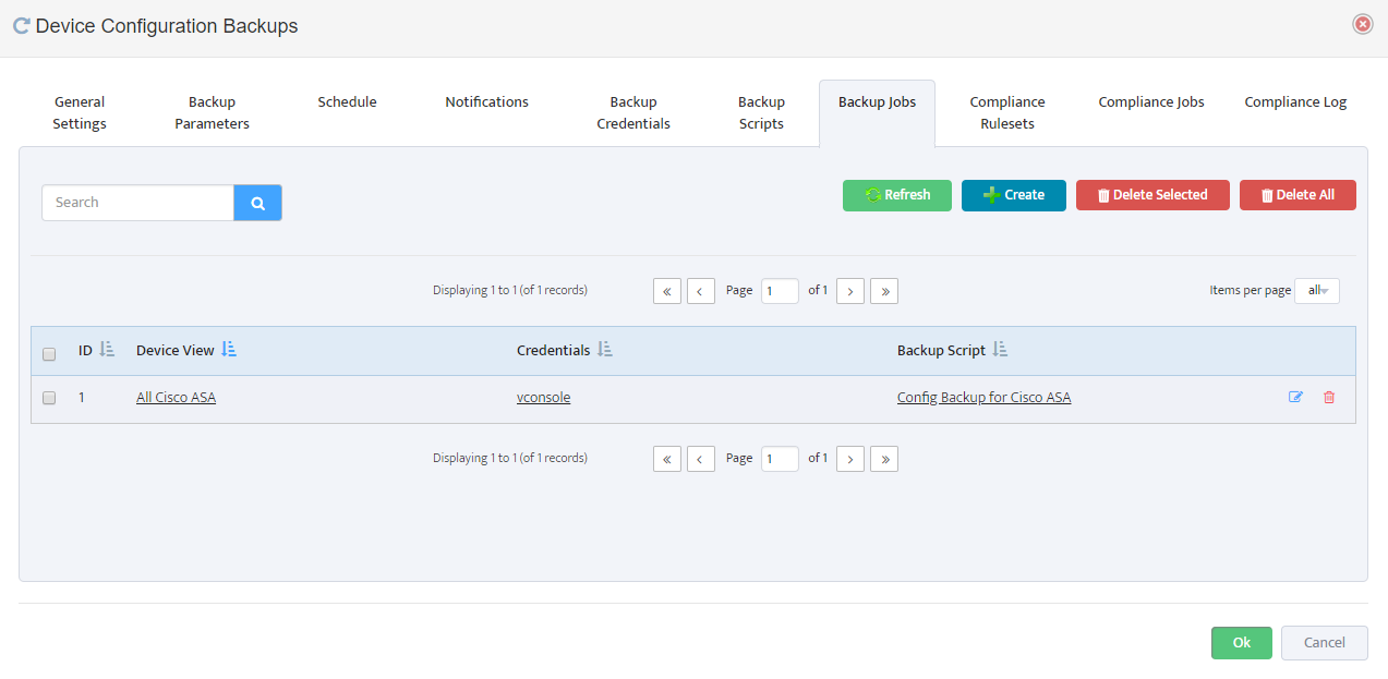
Next step is to create a Backup Job definition where you can combine Device View with specific Backup Credential Set and Backup Script.

To Create Backup Jobs, go to:

Settings → Device Configuration Backups → Backup Jobs

Enable Config Backup, Set Time and Miscellaneous Settings

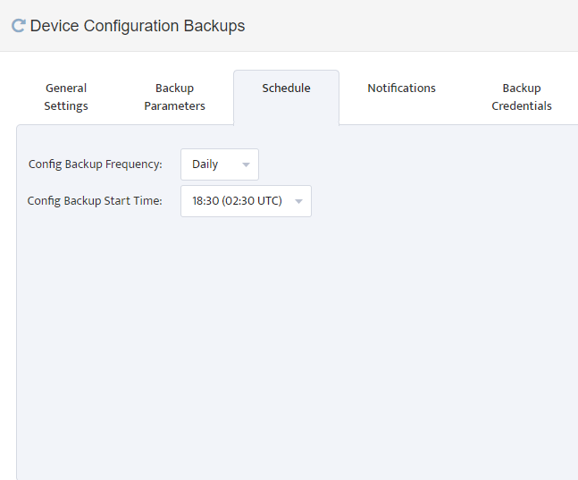
And final step is to define time for scheduled backup and to turn it ON.

To set a time for Configuration Backup, go to:

Settings → Device Configuration Backups → Schedule


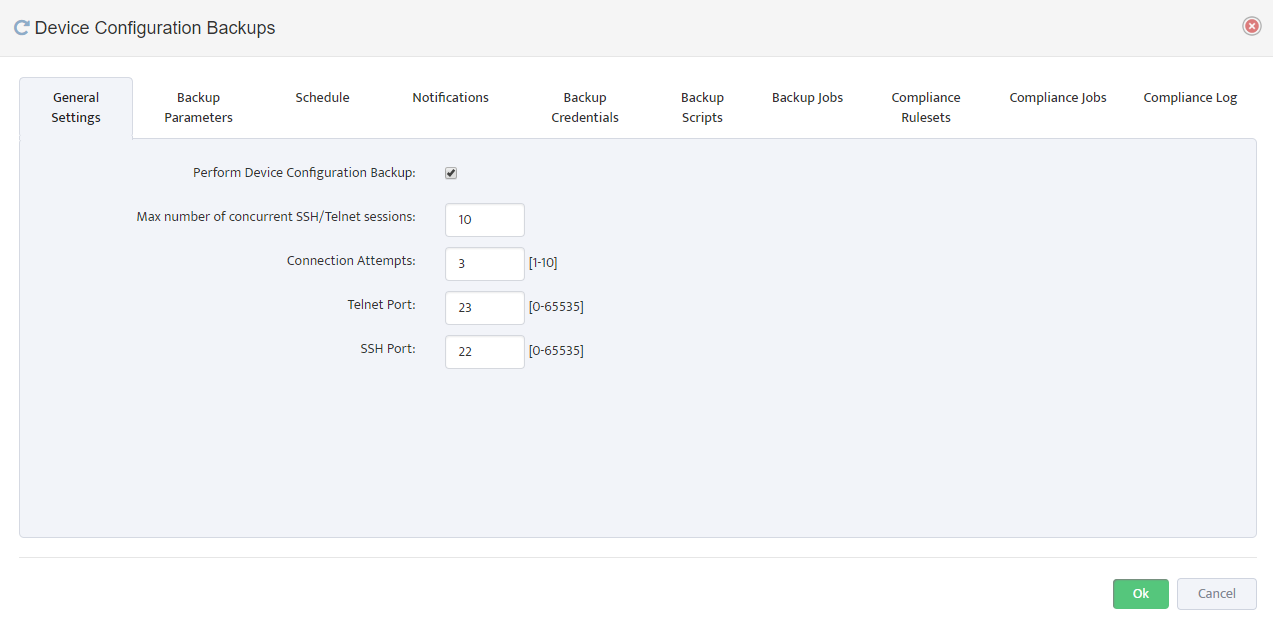
To enable configuration Backup go to:

Settings → Device Configuration Backups → General Settings


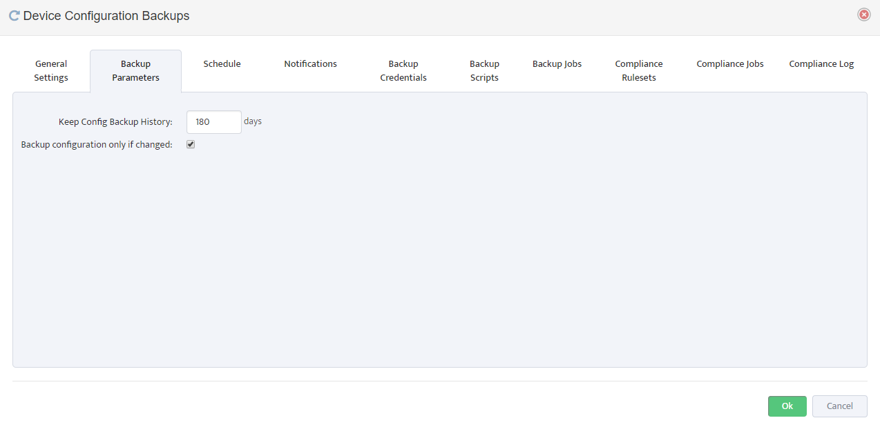
Additional Backup Parameters are available on “Backup Parameters” Tab where you can control for how long the backup files should be stored in DB

and whether you want you to backup up configuration if it has not changed since the last time it was backed up.


Note: Backup engine attempts SSH connection first and if SSH connection fails it will attempt a Telnet.


Initial IPv4 IPAM Configuration

Initial IPv4 IPAM Configuration

Step 1. Define your IPv4 Address Space.

Very first step in setting up your Nectus IPAM is to define your IPv4 Address Space.

Address Space is list of major subnets that represent all your address space that you

planning to use for IP address allocation.

Good examples of subnets that you normally list as your address space definition is

10.0.0.0/8

192.168.0.0/16

172.16.0.0/12

To complete your Address Space definition, go to:

Settings → General Settings → IPAM Integration (Tab: IPv4 Address Space)

Step 2: Add DNS Servers.

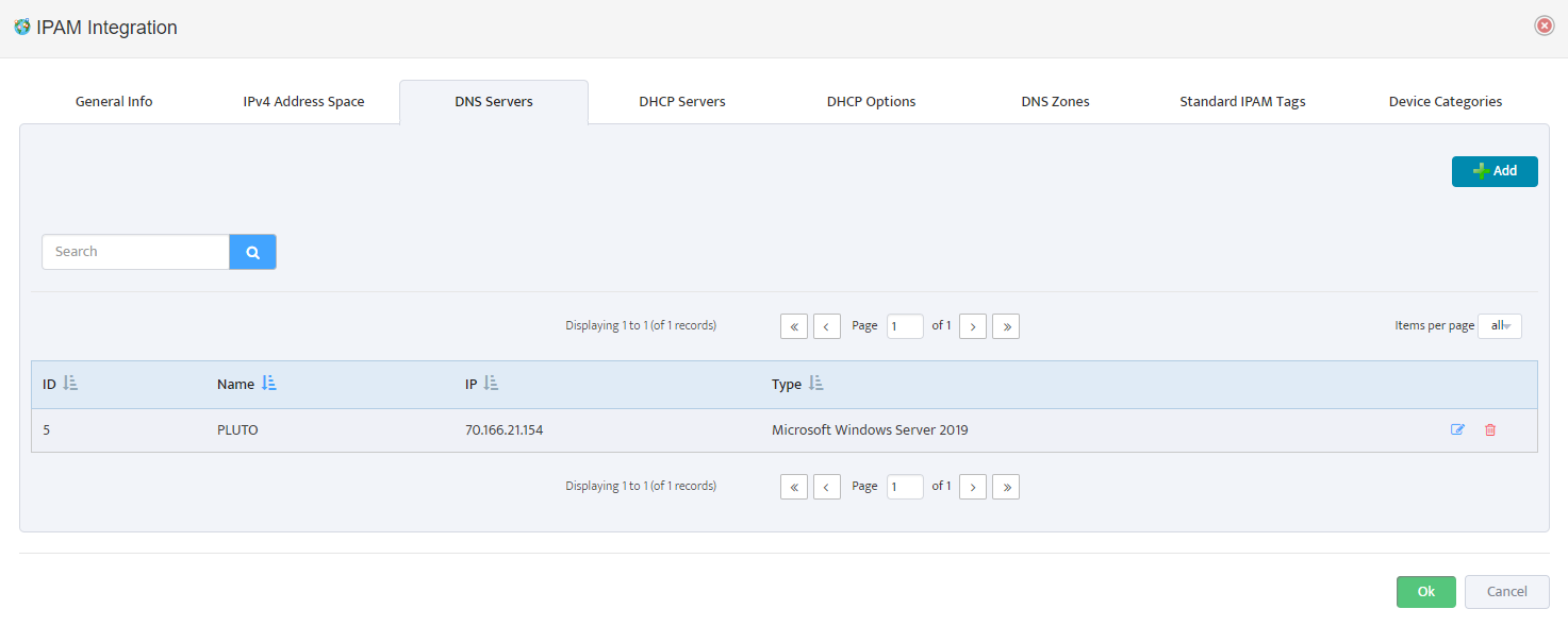
Next Step is to complete integration of your existing DNS Servers with Nectus IPAM

Add your DNS Servers to Nectus in:

Settings → General Settings → IPAM Integration (Tab: DNS Servers)

Note: Nectus currently only supports integration with Microsoft Windows based DNS Servers.

Integration with DNS Server allows Nectus to dynamically create DNS records for Static IP reservations and to Import existing DNS records into IPAM database.

For Nectus to be able to communicate with DNS Servers WMI Integration must be complete.

Complete WMI Integration in Settings → General Settings → WMI Integration

Step 3: Define your DNZ Zones

Next step after adding DNS Servers is to define your DNS Zones. You can manually add your DNS Zones to IPAM or import is from your DNS Servers.

To define your DNS Zones go to:

Settings → General Settings → IPAM Integration (Tab: DNS Zones)

Step 4: Add DHCP Servers

By adding your DHCP servers to Nectus IPAM your can access rich GUI interface for managing your DHCP Scopes, Reservations, Leases and DHCP Options.

Note: Nectus currently only supports integration with Microsoft Windows based DHCP Servers.

To add your DHCP Servers go to:

Settings → General Settings → IPAM Integration (Tab: DHCP Servers)

For Nectus to be able to communicate with DHCP Servers WMI Integration must be complete.

Complete WMI Integration in Settings → General Settings → WMI Integration

Step 5: Define Standard IPAM Tags

Nectus IPAM provide extensive list of Tags that can be used for any of the IPAM Subnets.

Current list of Standard Tags:

BGP AS Number

Customer Name

Stack

Datacenter

Context

VRF

Project

Environment

Application

Remote Office

To define your Standard IPAM Tags go to:

Settings → General Settings → IPAM Integration (Tab: Standard IPAM Tags)

Step 6: Create IPAM Container Tree

Now we are ready to create an IPAM Container Tree hierarchy where you will be keeping all of the subnets.

IPAM Container tree can be organized in any way that is suitable for your business model.

One of the common examples that can be used is State-City-Datacenter-Application model.

To start creating IPAM Container levels go to IPAM left-side panel and use context menu available from right-click of your mouse.

You can right click on any existing container level and create a sub-level container by using “Create New Container Level” option in context menu.

You can Create, Delete and Move any of the container levels by using corresponding option in context menu.

Step 7. Importing Subnets from DHCP Servers

Once IPAM container tree is created we are ready to start populating it with subnets.

We can manually add individual subnets to each container, but it is much easier to Import majority of your existing subnets from DHCP Server and from your IGP Routing Table.

The first place where we can import is from DHCP Servers.

Go to Tools → IPAM Tools


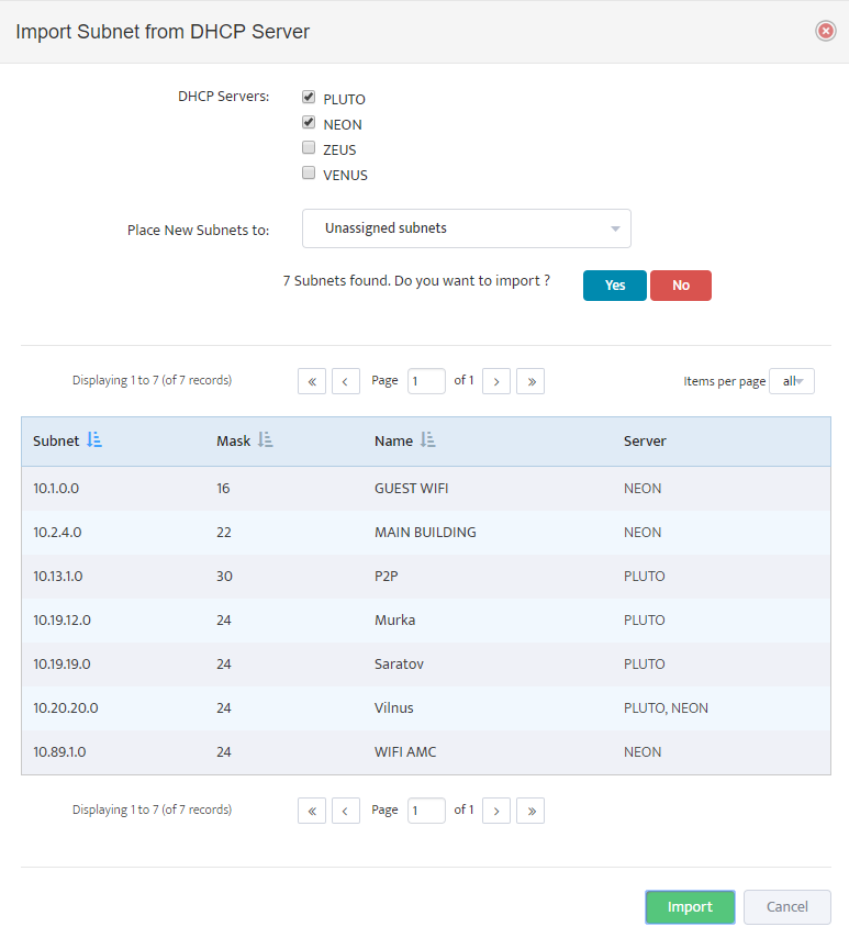
And press “Import Subnets from DHCP Servers”

Select DHCP Servers from which you want to import subnets and select Destination container where you want discovered subnets to be placed.

Nectus will display all discovered subnets and will ask for confirmation before importing it into the Database.

Step 8: Importing Subnets from IGP Routing Table

And last Step in Nectus IPAM Initial configuration is to Import all of your existing subnets from your IGP Routing Table.

Go to Tools→ IPAM Tools


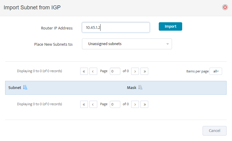
Press button “Import Subnets from routing Table”

Provide IP Address of any of your backbone routers, select destination container for imported subnets and press “Import” button.

Nectus will import all the subnets from IGP Routing Table starting from smallest (/32).

Nectus will not import any subnets that are overlapping with any of the subnets that are already present in Database.

Nectus will not import any of the BGP Subnets.

This Step concludes initial IPAM Configuration.

SNMP Device Status Color Codes

,

SNMP Device Status Color Codes

Nectus uses different colors to encode SNMP Device Status in Dashboards, Trees and Status Panels. There are three main color codes: Green, Red and Orange.

Green Color represent SNMP Device status when it is reachable by ICMP Probe and don’t have any critical interfaces Down.

Red Color represent SNMP Device status when it is not responding to ICMP Probe.

Orange Color represent SNMP Device that is reachable via ICMP but has at least one critical Interface down.

You can designate any Interface as critical by following these steps:

  1. Create Interface View that will contain all the Critical Interfaces
  2. Select this Interface View in Global Monitoring Settings

Critical Interfaces are marked by special “Star” icon in Interface List View

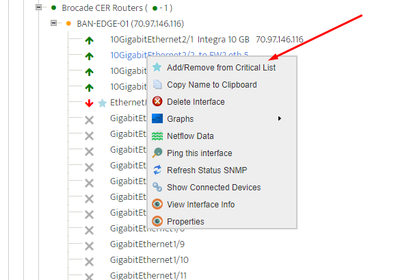
You can quickly add/remove Interface to Critical List by using Interface Context menu Option


How to collect Interface-VLAN membership info from Cisco Switch via SNMP (CISCO-VLAN-MEMBERSHIP-MIB)

,

How to collect Interface-VLAN membership info from Cisco Switch via SNMP (CISCO-VLAN-MEMBERSHIP-MIB)


CISCO-VLAN-MEMBERSHIP-MIB contain several usefull OIDs for collecting Interface VLAN membership information from Cisco Swithes

1.3.6.1.4.1.9.9.68.1.2.2.1.1 (vmVlanType)

1.3.6.1.4.1.9.9.68.1.2.2.1.2 (vmVlan)

1.3.6.1.4.1.9.9.68.1.2.2.1.3 (vmPortStatus)

1.3.6.1.4.1.9.9.68.1.2.2.1.4 (vmVlans)

1.3.6.1.4.1.9.9.68.1.2.2.1.5 (vmVlans2k)

1.3.6.1.4.1.9.9.68.1.2.2.1.6 (vmVlans3k)

1.3.6.1.4.1.9.9.68.1.2.2.1.7 (vmVlans4k)


Lets see what our LAB switch reports on these for Interface with ifIndex = [4]


OID VLAN Memership Type: 1.3.6.1.4.1.9.9.68.1.2.2.1.1

1 = static, 2 = dynamic, 3 = multiVlan

Output Example: ‘1.3.6.1.4.1.9.9.68.1.2.2.1.1.4’ => “1” (VLAN statically assigned to this port)


OID VLAN ID of the Port: 1.3.6.1.4.1.9.9.68.1.2.2.1.1

Output Example: ‘1.3.6.1.4.1.9.9.68.1.2.2.1.2.4′ => “104” (Port is assigned to VLAN 104)


OID Port Status: 1.3.6.1.4.1.9.9.68.1.2.2.1.3

1 = Inactive, 2 = Active, 3 = Shutdown

Output Example: ‘1.3.6.1.4.1.9.9.68.1.2.2.1.3.4’ => “2” (Port is Active)


How to collect list of VLANs from Cisco Switch via SNMP (CISCO-VTP-MIB)

,

How to collect list of VLANs from Cisco Switch via SNMP (CISCO-VTP-MIB)

CISCO-VTP-MIB contain several useful OID for collecting VLAN information from Cisco Switches


1.    1.3.6.1.4.1.9.9.46.1.3.1.1.1 (vtpVlanIndex)

2.    1.3.6.1.4.1.9.9.46.1.3.1.1.2 (vtpVlanState)

3.    1.3.6.1.4.1.9.9.46.1.3.1.1.3 (vtpVlanType)

4.    1.3.6.1.4.1.9.9.46.1.3.1.1.4 (vtpVlanName)

5.    1.3.6.1.4.1.9.9.46.1.3.1.1.5 (vtpVlanMtu)

6.    1.3.6.1.4.1.9.9.46.1.3.1.1.6 (vtpVlanDot10Said)

7.    1.3.6.1.4.1.9.9.46.1.3.1.1.7 (vtpVlanRingNumber)

8.    1.3.6.1.4.1.9.9.46.1.3.1.1.8 (vtpVlanBridgeNumber)

9.    1.3.6.1.4.1.9.9.46.1.3.1.1.9 (vtpVlanStpType)

10.    1.3.6.1.4.1.9.9.46.1.3.1.1.10 (vtpVlanParentVlan)

11.    1.3.6.1.4.1.9.9.46.1.3.1.1.11 (vtpVlanTranslationalVlan1)

12.    1.3.6.1.4.1.9.9.46.1.3.1.1.12 (vtpVlanTranslationalVlan2)

13.    1.3.6.1.4.1.9.9.46.1.3.1.1.13 (vtpVlanBridgeType)

14.    1.3.6.1.4.1.9.9.46.1.3.1.1.14 (vtpVlanAreHopCount)

15.    1.3.6.1.4.1.9.9.46.1.3.1.1.15 (vtpVlanSteHopCount)

16.    1.3.6.1.4.1.9.9.46.1.3.1.1.16 (vtpVlanIsCRFBackup)

17.    1.3.6.1.4.1.9.9.46.1.3.1.1.17 (vtpVlanTypeExt)

18.    1.3.6.1.4.1.9.9.46.1.3.1.1.18 (vtpVlanIfIndex)


Note that output from out Lab Switch did not return any values for first OID: 1.3.6.1.4.1.9.9.46.1.3.1.1.1


VLAN State: 1.3.6.1.4.1.9.9.46.1.3.1.1.2

1 = Operational, 2 = Suspended, 3 = mtuTooBigForDevice, 4 = mtuTooBigForTrunk

‘1.3.6.1.4.1.9.9.46.1.3.1.1.2.1.1’ => “1”

‘1.3.6.1.4.1.9.9.46.1.3.1.1.2.1.10’ => “1”

‘1.3.6.1.4.1.9.9.46.1.3.1.1.2.1.100’ => “1”

‘1.3.6.1.4.1.9.9.46.1.3.1.1.2.1.101’ => “1”

‘1.3.6.1.4.1.9.9.46.1.3.1.1.2.1.102’ => “1”

‘1.3.6.1.4.1.9.9.46.1.3.1.1.2.1.109’ => “1”

‘1.3.6.1.4.1.9.9.46.1.3.1.1.2.1.1000’ => “1”

‘1.3.6.1.4.1.9.9.46.1.3.1.1.2.1.1001’ => “1”

‘1.3.6.1.4.1.9.9.46.1.3.1.1.2.1.1002’ => “1”

‘1.3.6.1.4.1.9.9.46.1.3.1.1.2.1.1003’ => “1”

‘1.3.6.1.4.1.9.9.46.1.3.1.1.2.1.1004’ => “1”

‘1.3.6.1.4.1.9.9.46.1.3.1.1.2.1.1005’ => “1”


VLAN Type: 1.3.6.1.4.1.9.9.46.1.3.1.1.3

1 = Ethernet, 2 = FDDI, 3= TokenRing, 4 = FDDI, 5 = rtNet, 6 = Depreciated

‘1.3.6.1.4.1.9.9.46.1.3.1.1.3.1.1’ => “1”

‘1.3.6.1.4.1.9.9.46.1.3.1.1.3.1.10’ => “1”

‘1.3.6.1.4.1.9.9.46.1.3.1.1.3.1.100’ => “1”

‘1.3.6.1.4.1.9.9.46.1.3.1.1.3.1.101’ => “1”

‘1.3.6.1.4.1.9.9.46.1.3.1.1.3.1.102’ => “1”

‘1.3.6.1.4.1.9.9.46.1.3.1.1.3.1.109’ => “1”

‘1.3.6.1.4.1.9.9.46.1.3.1.1.3.1.1000’ => “1”

‘1.3.6.1.4.1.9.9.46.1.3.1.1.3.1.1001’ => “1”

‘1.3.6.1.4.1.9.9.46.1.3.1.1.3.1.1002’ => “2”

‘1.3.6.1.4.1.9.9.46.1.3.1.1.3.1.1003’ => “3”

‘1.3.6.1.4.1.9.9.46.1.3.1.1.3.1.1004’ => “4”

‘1.3.6.1.4.1.9.9.46.1.3.1.1.3.1.1005’ => “5”


VLAN Name: 1.3.6.1.4.1.9.9.46.1.3.1.1.4

‘1.3.6.1.4.1.9.9.46.1.3.1.1.4.1.1’ => “default”

‘1.3.6.1.4.1.9.9.46.1.3.1.1.4.1.10’ => “VLAN0010”

‘1.3.6.1.4.1.9.9.46.1.3.1.1.4.1.100’ => “VLAN0100”

‘1.3.6.1.4.1.9.9.46.1.3.1.1.4.1.101’ => “VLAN0101”

‘1.3.6.1.4.1.9.9.46.1.3.1.1.4.1.102’ => “vlan102”

‘1.3.6.1.4.1.9.9.46.1.3.1.1.4.1.109’ => “VLAN0109”

‘1.3.6.1.4.1.9.9.46.1.3.1.1.4.1.1000’ => “VLAN1000”

‘1.3.6.1.4.1.9.9.46.1.3.1.1.4.1.1001’ => “VLAN1001”

‘1.3.6.1.4.1.9.9.46.1.3.1.1.4.1.1002’ => “fddi-default”

‘1.3.6.1.4.1.9.9.46.1.3.1.1.4.1.1003’ => “token-ring-default”

‘1.3.6.1.4.1.9.9.46.1.3.1.1.4.1.1004’ => “fddinet-default”

‘1.3.6.1.4.1.9.9.46.1.3.1.1.4.1.1005’ => “trnet-default”
 

How to collect list of MAC addresses from Cisco Switch via SNMP (dot1dTpFdbEntry)

,

How to collect list of MAC addresses from Cisco Switch via SNMP (dot1dTpFdbEntry)

One of the ways to get list of MAC addresses from the forwarding table of Cisco switch is via SNMP MIB: dot1dTpFdbEntry

This MIB branch contain three OIDs:

1.3.6.1.2.1.17.4.3.1.1 (dot1dTpFdbAddress)

1.3.6.1.2.1.17.4.3.1.2 (dot1dTpFdbPort)

1.3.6.1.2.1.17.4.3.1.3 (dot1dTpFdbStatus)

1.3.6.1.2.1.17.4.3.1.1 (dot1dTpFdbAddress) contain list of MAC addresses in Binary format

1.3.6.1.2.1.17.4.3.1.2 (dot1dTpFdbPort) contain IfIndex value of the interface associated with each MAC Address

1.3.6.1.2.1.17.4.3.1.3 (dot1dTpFdbStatus) contain Status code which gives information how each MAC was learned by the switch.


To get list of MAC address perform SNMP Get-Bulk request for “.1.3.6.1.2.1.17.4.3.1.1”
Here is the Example of output from our LAB Switch:

‘1.3.6.1.2.1.17.4.3.1.1.0.21.198.146.146.151’ => “ƒ’—”

‘1.3.6.1.2.1.17.4.3.1.1.0.25.185.178.231.213’ => “¹²çÕ”

‘1.3.6.1.2.1.17.4.3.1.1.0.33.216.202.216.128’ => “!ØÊ؀”

‘1.3.6.1.2.1.17.4.3.1.1.0.34.144.251.146.97’ => “”û’a”

‘1.3.6.1.2.1.17.4.3.1.1.0.80.86.156.43.191’ => “PVœ+¿”

‘1.3.6.1.2.1.17.4.3.1.1.0.80.86.156.49.102’ => “PVœ1f”

‘1.3.6.1.2.1.17.4.3.1.1.0.80.86.156.69.113’ => “PVœEq”


Notice that actual MAC Addresses returned look like some garbage characters but those are actually MAC address in ASCII format that needs to be converted to HEX to get a conventional xx:xx:xx:xx:xx:xx style.

Lets take last line: ‘1.3.6.1.2.1.17.4.3.1.1.[0.80.86.156.69.113]’ => “PVœEq”

If we take ASCII text (PVœEq) and convert to HEX,  we will get  50:56:9C:45:71

If we take Decimal [0.80.86.156.69.113] and convert to HEX, we will get 0:50:56:9C:45:71

So we have a MAC address on both sides.


To get list of associated Ports for each MAC address perform SNMP Get-Bulk request for “.1.3.6.1.2.1.17.4.3.1.2”

Here is the Example of output from our LAB Switch:

‘1.3.6.1.2.1.17.4.3.1.2.0.21.198.146.146.151’ => “2”

‘1.3.6.1.2.1.17.4.3.1.2.0.25.185.178.231.213’ => “2”

‘1.3.6.1.2.1.17.4.3.1.2.0.33.216.202.216.128’ => “1”

‘1.3.6.1.2.1.17.4.3.1.2.0.34.144.251.146.97’ => “1”

‘1.3.6.1.2.1.17.4.3.1.2.0.80.86.156.43.191’ => “2”

‘1.3.6.1.2.1.17.4.3.1.2.0.80.86.156.49.102’ => “2”

‘1.3.6.1.2.1.17.4.3.1.2.0.80.86.156.69.113’ => “2”

Values returned represent IfIndex values for corresponding Interfaces associated with each MAC Address. You need to use [ID substring] to match ifIndex value to MAC Address.

And finally, to get a Status code to each MAC address perform SNMP Get-Bulk Request for 1.3.6.1.2.1.17.4.3.1.3


Example of output from our LAB Switch:

‘1.3.6.1.2.1.17.4.3.1.3.0.21.198.146.146.151’ => “3”

‘1.3.6.1.2.1.17.4.3.1.3.0.25.185.178.231.213’ => “3”

‘1.3.6.1.2.1.17.4.3.1.3.0.33.216.202.216.128’ => “3”

‘1.3.6.1.2.1.17.4.3.1.3.0.34.144.251.146.97’ => “3”

‘1.3.6.1.2.1.17.4.3.1.3.0.80.86.156.43.191’ => “3”

‘1.3.6.1.2.1.17.4.3.1.3.0.80.86.156.49.102’ => “3”

‘1.3.6.1.2.1.17.4.3.1.3.0.80.86.156.69.113’ => “3”

Possible Values codes are

1 = Other

None of the following. This would include the case where some other MIB object (not the corresponding instance of dot1dTpFdbPort, nor an entry in the dot1dStaticTable)

is being used to determine if and how frames addressed to the value of the corresponding instance of dot1dTpFdbAddress are being forwarded.

2 = Invalid

This entry is no longer valid (e.g., it was learned but has since aged out), but has not yet been flushed from the table.

3 = Learned

The value of the corresponding instance of dot1dTpFdbPort was learned and is being used.

4 = Self

The value of the corresponding instance of dot1dTpFdbAddress represents one of the bridge’s addresses.

The corresponding instance of dot1dTpFdbPort indicates which of the bridge’s ports have this address.

5 = Mgmt

The value of the corresponding instance of dot1dTpFdbAddress is also the value of an existing instance of dot1dStaticAddress.


Important Note: This process may need to be adjusted if  “per-VLAN” SNMP Contexts being used. In that case you must repeat this process separately for each VLAN by adding “@n” to SNMP community string where “n” is the VLAN ID.

How to Add/Discover single SNMP Device in Nectus

,

How to Add/Discover Single SNMP Device in Nectus

Starting from Version 1.2.49 process of adding single device to Nectus database was greatly simplified and improved.

To discover single SNMP device open in Main menu Tools → Manual Discovery Start

In Manual Discovery window Select Partial Discovery and specify single IP address with /32 Mask for Subnet.

Press Start Button to start a Discovery process.

After Discovery starts you can monitor its progress in Discovery log located in

Top Menu Logs → Discovery Log

Each Discovery Job will have individual line in Discovery log

Manually Initiated Discoveries will have string “Manual” in Type Column as opposed to “Schedule” to scheduled automatic discoveries.

Each Discovery log record contain information about how many overall and new devices were discovered at each Discovery job.

If your manual Discovery job shows “0” New SNMP Devices discovered then you need to verify IP address, SNMP configuration and overall availability of device that you want to discover.